Binary Logic, Number systems, Gates
Number Systems
It is said that the concept of "zero" was given to the world by ancient Indians. Why is this concept so important ? Does this mean that in other number systems, there was no concept of "zero" ?
What we call the significance of "zero" is really the important insight about the position of digits in a number. In other words, the value of each digit in a number is determined not merely by the magnitude of the digit, but also by its position in the number; for each subsequent position contributes by the next higher POWER of the BASE of the counting system to the digit. We are familiar with the decimal system, which is in BASE 10, using [0..9]. Therefore, in the numbers 05 and 50 (both in base 10), while the "5" contributes to the magnitude of the number 05 by only ( 5 * 100 ), it contributes by ( 5 * 101 ) in 50.
The gift of the Indian (or Arabic) numeral system was not due to the value of the base being 10, but the concept of positional "significance" of the digits in a number. Would this property be retained in counting systems in other bases ?
Yes.
For instance, we could work out all numerical work in base 2 (binary), using [0..1], or in base 8 (octal), using [0..7] or in base 16 (hexadecimal, or hex), using [0..F]. The table below counts up to sixteen in each of these systems.
Decimal Binary Octal Hex
0000 00000 0000 0000
0001 00001 0001 0001
0002 00010 0002 0002
0003 00011 0003 0003
0004 00100 0004 0004
0005 00101 0005 0005
0006 00110 0006 0006
0007 00111 0007 0007
0008 01000 0010 0008
0009 01001 0011 0009
0010 01010 0012 000A
0011 01011 0013 000B
0012 01100 0014 000C
0013 01101 0015 000D
0014 01110 0016 000E
0015 01111 0017 000F
0016 10000 0020 0010
In any such system, it is conventional to write the number with the most significant digit at the leftmost position, and the least significant one at the rightmost. We shall follow the following convention to represent numbers: N
b will represent number N in base b.It is easy to convert numbers from one base to another:
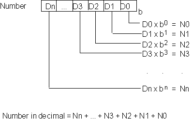
Figure 4.1 shows the relation between a number in base "b" to its decimal equivalent. How do we convert a decimal number to one in base "b" ?

Figure 4.1. Converting numbers between bases
The method can be understood by looking at the structure of the figure above, also. Let the number in decimal be N
10.Now, N
10 = [ bn x Dn + ... + b3 x D3 + b2 x D2 + b1 x D1 ] + D0
The term inside the [ ..] is clearly divisible by "b". therefore the least significant bit in the base-b expansion of N
10 can be obtained by getting the remainder after dividing it by "b". Further, the integral part of the quotient is of the form:b
n-1 x Dn + ... + b2 x D3 + b1 x D2 + D1;By dividing again by "b", we can get the second least significant digit, D1.. and so on.
Example: convert 25
10 to Octal.
As a direct result of the above, we can see that anything that can be done using the decimal number system can be done in any other base also.
This is good for number computations; but how about data ? Most information that human beings process can be described either using languages (e.g. English, Cantonese..), or using numbers. Can we do without one of these two also ?
Yes. Most languages that humans use have a finite alphabet. What this means is that ALL the symbols (alphabet, punctuation, other characters such as $, % etc.) that are used by a language can be listed in a finite list. Therefore, if we take all of these symbols, and assign numerical code values to them, then anything in the language can be represented as a list of numbers, which denote the position in the list of each subsequent symbol. Even the symbols for our numbers [ the symbols 0, 1, .., 9 for the decimal system] are assigned a code value. This is why the coding schemes are called alphanumeric codes.
The most popular of coding schemes are ASCII (American Standard Code for Information Exchange) and EBCDIC (Extended Binary-Coded Decimal Interchange Code). the ASCII code is shown in the tables below:
Decimal characters
| 0 NUL| 1 SOH| 2 STX| 3 ETX| 4 EOT| 5 ENQ| 6 ACK| 7 BEL|
| 8 BS | 9 HT | 10 NL | 11 VT | 12 NP | 13 CR | 14 SO | 15 SI |
| 16 DLE| 17 DC1| 18 DC2| 19 DC3| 20 DC4| 21 NAK| 22 SYN| 23 ETB|
| 24 CAN| 25 EM | 26 SUB| 27 ESC| 28 FS | 29 GS | 30 RS | 31 US |
| 32 SP | 33 ! | 34 " | 35 # | 36 $ | 37 % | 38 & | 39 ' |
| 40 ( | 41 ) | 42 * | 43 + | 44 , | 45 - | 46 . | 47 / |
| 48 0 | 49 1 | 50 2 | 51 3 | 52 4 | 53 5 | 54 6 | 55 7 |
| 56 8 | 57 9 | 58 : | 59 ; | 60 < | 61 = | 62 > | 63 ? |
| 64 @ | 65 A | 66 B | 67 C | 68 D | 69 E | 70 F | 71 G |
| 72 H | 73 I | 74 J | 75 K | 76 L | 77 M | 78 N | 79 O |
| 80 P | 81 Q | 82 R | 83 S | 84 T | 85 U | 86 V | 87 W |
| 88 X | 89 Y | 90 Z | 91 [ | 92 \ | 93 ] | 94 ^ | 95 _ |
| 96 ` | 97 a | 98 b | 99 c |100 d |101 e |102 f |103 g |
|104 h |105 i |106 j |107 k |108 l |109 m |110 n |111 o |
|112 p |113 q |114 r |115 s |116 t |117 u |118 v |119 w |
|120 x |121 y |122 z |123 { |124 | |125 } |126 ~ |127 DEL|
Octal characters
|000 NUL|001 SOH|002 STX|003 ETX|004 EOT|005 ENQ|006 ACK|007 BEL|
|010 BS |011 HT |012 NL |013 VT |014 NP |015 CR |016 SO |017 SI |
|020 DLE|021 DC1|022 DC2|023 DC3|024 DC4|025 NAK|026 SYN|027 ETB|
|030 CAN|031 EM |032 SUB|033 ESC|034 FS |035 GS |036 RS |037 US |
|040 SP |041 ! |042 " |043 # |044 $ |045 % |046 & |047 ' |
|050 ( |051 ) |052 * |053 + |054 , |055 - |056 . |057 / |
|060 0 |061 1 |062 2 |063 3 |064 4 |065 5 |066 6 |067 7 |
|070 8 |071 9 |072 : |073 ; |074 < |075 = |076 > |077 ? |
|100 @ |101 A |102 B |103 C |104 D |105 E |106 F |107 G |
|110 H |111 I |112 J |113 K |114 L |115 M |116 N |117 O |
|120 P |121 Q |122 R |123 S |124 T |125 U |126 V |127 W |
|130 X |131 Y |132 Z |133 [ |134 \ |135 ] |136 ^ |137 _ |
|140 ` |141 a |142 b |143 c |144 d |145 e |146 f |147 g |
|150 h |151 i |152 j |153 k |154 l |155 m |156 n |157 o |
|160 p |161 q |162 r |163 s |164 t |165 u |166 v |167 w |
|170 x |171 y |172 z |173 { |174 | |175 } |176 ~ |177 DEL|
In the tables the numerical code of each symbol is shown. Only 128 numbers are sufficient to describe all the symbols.
If we used a decimal system, how many digits would we need to encode one character ?
What if we use the binary system ?
The binary system is very significant in computer systems. If we are to use electronic systems to store/manipulate information, it is clear that some electrical quantity has to be measured, and its value be correlated to the information by some kind of a one-to-one mapping. In electronics, this electrical quantity is the potential difference between two terminals, or the Voltage. Thus all information has to be transformed in terms of Voltage levels. It is extremely difficult to design electronic equipment that could perform various operations using more than two voltage levels in a consistent fashion. However, this could be done by using two levels (usually distinguished by Zero Vs Positive voltage, or in some cases by +V Vs -V volts). The two distinguishable states ( presence of a Voltage difference or absence of it) are used to designate two signal values: 0 or 1. But these two values, 0 and 1, are sufficient to describe any information using a binary code.
Binary Logic and Gates
Most of the processing done by the computer uses just a few basic electronic devices, which perform very simple functions. The most important of these devices are logic gates. These gates are devices which have one of two voltage levels as their output: 0 V or (typically) 5 V, based on the voltage applied to their input terminals. They are designed so that the relation between the input(s) and outputs replicates a mathematical system called binary logic. Each Integrated Chip (IC) in a computer contains thousands of binary gates. We shall introduce binary logic as a subset of a wider theory called switching theory, which is popularly known as Boolean Algebra [After George Boole, whose work is considered as the foundation for modern computers].
Boolean algebra is an algebra of variables which can have only one of two possible values. For convenience, we shall take these values (called the "state" of the variable) as 0 and 1. Three basic operations are defined in the algebra: conjunction (denoted by
L), disjunction (denoted V), and negation (denoted by a bar above the symbol). The operators are defined as follows:
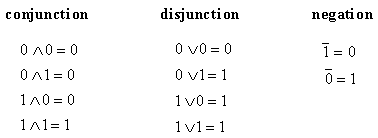
The operators have a direct correlation with electronic gates that we shall use.
conjunction: the AND gate.
disjunction: the OR gate.
negation: the NOT gate.
Figure 4.2 shows a typical function for a gate using a cassette player motor switch as a metaphor. Figure 4.3 shows the pictorial representation of these gates and their behavior.

Figure 4.2. Control circuit for a cassette motor
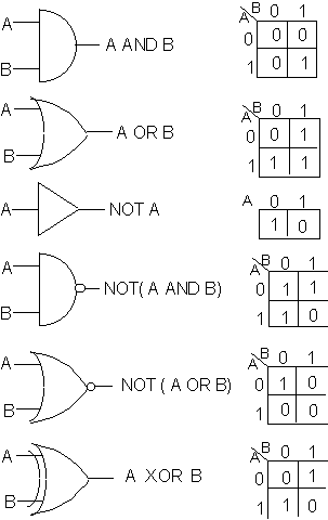
Figure 4.3. Common electronic gates and their output functions.
We shall denote variables in the algebra by upper case letters of the alphabets [A..Z]. The theory of Boolean algebra lays down rules which govern how to build up "expressions" using these variables, constants, and operators to construct meaningful (or valid) expressions. For any valid expression, we can determine the truth value corresponding to the values that the variables can take. A common device used to systematically determine all possible values an expression is a truth table. The truth tables corresponding to the three operators are shown if figure 4.4.
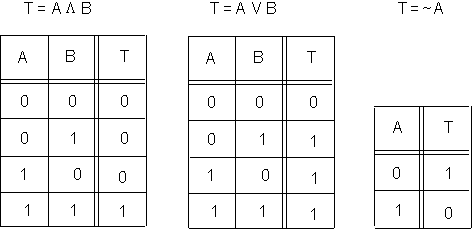
Figure 4.4. Truth Tables corresponding to the three operators
Operations on binary numbers:
We have already seen how all information can be represented using 128 characters, which can be represented by 7 binary digits (called bits). A set of eight bits makes what is called a byte. The eighth digit is used differently in different applications. One common use for the eighth bit is for error correction, as a parity checker. The binary representation in a parity-checking system looks like:
![]()
where the binary number is B1B2..B7, and "p" is the parity bit. A given system operates under either even parity, odd parity, or no parity (in which case no error checking is done using parity). In odd parity system, the number of 1's in the ASCII representation of the character are counted, and if the total number of 1's is odd, p is set to 0, else it is 1. Thus the total number of 1's in the 8-bit representation of each character is odd.
In an even parity system, p = 0 if the number of 1's in the 7-bit representation is even, else p = 1.
When communicating a message between two devices, the parity bit is used as a simple means of checking if the data being received is not corrupted.
Within the processor, the extra bit is used for other purposes.
One operation of interest on binary representations is the 2's complementation.
The 2's complement of a number is derived in the following way:
We start from the least significant digit, and copy bit-by-bit till we reach the first "1". The first "1" (the least significant "1") is copied. All the remaining digits are inverted ( a "0" is converted to "1", and vice versa.)
Example:
Binary number, b = 0010110
2's complement of b = 1101010
The importance of this seemingly odd operation is easily explained, and the explanation also gives insight into the real meaning of the operation. In a computer, any number needs to be represented in binary. However, due to limitations of various kinds, we can only allow the representation to be of finite length (e.g. 8, 16, or 32 bits are common limits, though some computers can handle 64 bit integers). This finite representation causes two problems, both of which will be explained for a simpler case where each number is allowed to have a maximum of 4 bits.

The first problem is in example (b), where the sum of the numbers exceeds the number of digits we allow in our representation. This is a problem of overflow.
The second one concerns the example (d), where the subtraction results in a "borrow" from a significant digit that does not exist! Note that in our 4-bit representation, we can only talk of numbers from 0-15. The computation in (d) is (3 - 9 = -6). There is no way to represent negative numbers. (the result is -1x24 + 1010).
It appears that we need extra bits to represent negative numbers, and also to get correct answers from our math. Let us therefore add one extra bit to the representation, and also a 1-bit flag. We shall use the flag each time there is an overflow, thereby letting us know that the real answer to our computation is the result we got, plus 1x24. That takes care of the overflow problem.
What about negative numbers ? Here, we adopt a new representation: we use the extra bit (by convention, the most significant bit) to denote if a number is negative. In fact, we go one step further, and express any negative number in the 2's complement form. This (1) ensures that the msb is 1; and (2) allows for a subtraction to become an addition process !
Let us take a few examples to clarify this:
|
number (nd) |
binary (nb) |
-2's complement ( - n ) |
|
3 |
0 : 0011 |
1 : 1101 |
|
5 |
0 : 0101 |
1 : 1011 |
|
7 |
0 : 0111 |
1 : 1001 |
|
8 |
0 : 1000 |
1 : 1000 |
What is :
5 - 7 ?
-3 - 3 ?
8 - 3 ?
Boolean Algebra
Boolean algebra is a mathematical branch that studies the manipulation of variables and constants that can have only one of two values. It was developed by George Boole, hence the name. The parallel between binary logic and Boolean algebra is close, and this was why much of the theoretical background for the functioning of modern computers is based on Boolean algebra. As in real- and complex- algebra that we are familiar with, Boolean algebra is built up of a set of symbols ( constants 1,0; symbols (, ), V,
L, =, ¬; variables A, B.. etc.). The operators (V, L, ¬) are defined the same as in binary logic. Further, the algebra defines a set of rules that can be used to construct statements, whose truth value can be tested. Any statement which is true for all values of the variables in it is said to be a theorem.The theorems of Boolean algebra can be derived using the definitions of the operators and the truth table approach. Some of the important theorems are listed below.

For the sake of simplicity of expression, we use a shorthand notation for the operators. The '![]() ' operator will be implicitly assumed for any variables placed contiguously. Thus
' operator will be implicitly assumed for any variables placed contiguously. Thus ![]() will be written as AB. Also, the parentheses will be introduced in expressions, with the usual meaning to denote the order of evaluation. Up till now, we have seen one variable expressions. Now we study expressions of more variables.
will be written as AB. Also, the parentheses will be introduced in expressions, with the usual meaning to denote the order of evaluation. Up till now, we have seen one variable expressions. Now we study expressions of more variables.
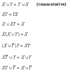
and the famous (and very useful) De Morgan's theorems:

Many of the above can easily be verified by using a truth table. Others can be derived from the earlier verified ones.
The purpose of learning these theorems, and Boolean algebra is so that we can manipulate Boolean expressions and derive equivalent, simplified forms given a more complex form. Since we shall eventually use such logic expressions in controlling automation of devices operating together, if we can derive simple expressions that have the same output as complicated ones, the resulting implementation will be cheaper, and less error prone.
There are two methods to simplify expressions, the algebraic method, and Karnaugh Maps.
The algebraic method uses the theorems shown above (and other ones derived using these) to simplify expressions. It shall be demonstrated by the following example.
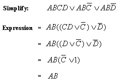
How many gates would we need to implement the original expression ?
How many are needed to implement the equivalent expression ?
The algebraic method requires some insight to simplify some more complicated expressions. The other method, using Karnaugh Maps, is a more systematic approach to simplifying Boolean expressions. The Karnaugh method is a graphical method.
Step A: constructing a Karnaugh map.
The Karnaugh map is a matrix containing 2
n elements, where n is the number of variables in the expression. Figure 4.5 shows the Karnaugh maps for expressions of two, three and four variables.
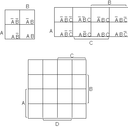
Figure 4.5. Karnaugh maps for 2, 3, and 4 variables
Any cell in the map is said to be adjacent to another if the two share an edge, or, if the two cells are along opposite borders of the same row/column. The distribution of the labels of the cells is such that each cell differs from any of its adjacent cells in precisely one variable.
How is the Karnaugh map used to simplify expressions ? The method is illustrated with the aid of an example, and then summarized in an algorithmic fashion.
Consider a function T, defined by:
![]()
We can see that T is a disjunction of eight conjunction terms. If any of these eight terms has a value of 1, T shall be 1. So we insert a 1 in each cell corresponding to these eight terms of the Karnaugh map. Note that the term ![]() contributes TWO 1's, since its value shall be 1 irrespective of whether A=0 or A=1. Any cell which doesn't have a 1 is filled with a 0.
contributes TWO 1's, since its value shall be 1 irrespective of whether A=0 or A=1. Any cell which doesn't have a 1 is filled with a 0.
Once the cells are filled, the next step is to loop adjacent squares containing a 1 into blocks having 2, 4, or 8 cells. Blocks have to be rectangular or square in shape, and must contain all 1's. At the end of the looping process, each cell with a 1 must be a part of some block. Also, the number of blocks must be as small as possible, and the blocks must be as large as possible. Figure 4.6 shows how this is done for our particular example.
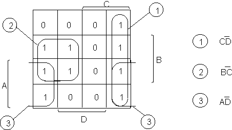
Figure 4.6. The Karnaugh map for simplification of T.
The address corresponding to each block is then formulated by observation. The address of each block is a term comprised of a conjunction of a set of variables (or their negation). Note that each 2-block eliminates one variable; each 4-block eliminates 2 variables, and each 8-block eliminates 3 variables. The addresses corresponding to the blocks in the example are shown in figure 4.6 above. The resulting simplified expression equivalent to the function is therefore obtained as:
![]()
In general, there may be more than one way to create blocks within the Karnaugh map. Which layout is the best ? In other words, which promises to yield the simplest expression (requiring a minimal number of gates) ? The algorithm which results in such breakdown is summarized below.
A prime implicant is defined as a block which is not entirely included in a larger block. In the earlier example of Figure 4.6, we could use a 2-block corresponding to ![]() but that would not be a prime implicant, since it is entirely contained in the larger block (1). An essential prime implicant is defined as a prime implicant which contains at least one cell with a 1 that CAN NOT be included in any other prime implicant. Each of the three cells in the example are essential prime implicants. [Note that the cell
but that would not be a prime implicant, since it is entirely contained in the larger block (1). An essential prime implicant is defined as a prime implicant which contains at least one cell with a 1 that CAN NOT be included in any other prime implicant. Each of the three cells in the example are essential prime implicants. [Note that the cell ![]() is a prime implicant, but not an essential prime implicant.]
is a prime implicant, but not an essential prime implicant.]
The optimum procedure involves first identifying and marking off all the essential prime implicants in a Karnaugh map. At the end of this block-ing, if any cells containing a 1 remain un-blocked, these shall be blocked using prime cells till all cells with a 1 are part of some block.
There is one more aspect about Karnaugh maps that arises in practical situations of automation. This is when some combination of the state of input variable(s) is not pertinent to the output function we are looking at. In such a case, we "don't care" about this combination of states, and in the corresponding cell of the Karnaugh map, we are free to put in either a 1 or a 0. We enter a special symbol in such cells:
F (which looks like a 1 superimposed on a 0), and use the cell only if it helps to simplify the final expression.
For example, assume we are designing the controls of an elevator. If the elevator is going up, it triggers a switch, A. If it is going down, it triggers a switch, B. There are other switches in the entire system, but let us concentrate on A and B. The state ![]() denotes that the elevator is going up (and not going down). Similarly,
denotes that the elevator is going up (and not going down). Similarly, ![]() denotes that the elevator is neither going up, nor down: i.e. it is standing. But what about the state AB ? Clearly, as long as our sensors are working fine, this state can never occur in reality. Therefore, in the Karnaugh map for the function which controls the elevator, any state with a label that has AB can be filled in with a
denotes that the elevator is neither going up, nor down: i.e. it is standing. But what about the state AB ? Clearly, as long as our sensors are working fine, this state can never occur in reality. Therefore, in the Karnaugh map for the function which controls the elevator, any state with a label that has AB can be filled in with a
In conclusion, let us summarize the methodology:
1. Identify input variables and the output variable in the problem, and formulate the expression which replicates the logic function desired.
2. Simplify the expression so that it is a disjunction of purely conjunctive terms.
3. Make the Karnaugh map depending on the number of variables.
4. Fill a 1 in the cell(s) corresponding to each term, and
F where applicable.5. Identify and "block" each essential prime implicant.
6. If any un-blocked "1" cells remain, create corresponding prime implicant.
7. Construct the output function as a disjunction of conjunctive terms corresponding to each implicant.