Appendix to Pneumatics
1. A Typical Pneumatic System
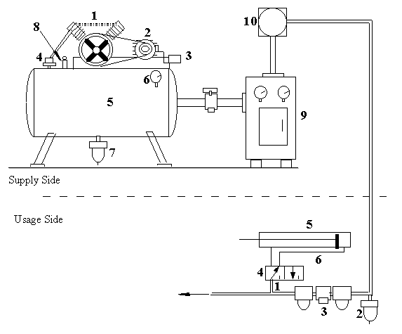
The figure below shows typical elements of a pneumatic system, and brief descriptions of the major components.
The system has two aspects: the supply side has hardware and controls which supply the compressed air. On the usage side are the components which use the compressed air to do some (automated, controlled) work. The components are described below.
Supply Side Legend:
1. Compressor: Air is taken in at atmospheric pressure, and compressed to a high pressure. The compressor can be driven by an electric motor (as shown) or by an internal combustion engine driven by diesel/petrol.
2. Electric motor: This supplies the electric energy, which is transformed into mechanical energy in the form of compressed air by the compressor.
3. Pressure switch: This controls the electric motor by sensing the pressure in the supply tank. When the pressure in the tank rises to the maximum set temperature, the motor is stopped. When the tank pressure goes below a set level, the motor again starts.
4. Check Valve: It allows the compressed air to flow from the compressor to the tank. It also disallows any air from the tank to leak back into the compressor.
5. Tank: This is where the high pressure air is stored.
6. Pressure Gauge: This is a simple sensor which can sense the tank pressure and indicates this value on the dial.
7. Drain: The drain removes all condensed water in the tank to the outside.
8. Safety Valve: In case the pressure in the tank exceeds the maximum set pressure (due to malfunction of the motor controls, for example), the safety valve blows and releases the tank pressure.
9. Refrigerated Air Dryer: This refrigerator system cools the air to a few degrees above the water freezing point. This condenses all moisture in the air to condense. Thus the air supplied to all downstream systems is totally dry, preventing any possible corrosion damage.
Usage Side Legend:
1. Air Take Off: For consumers, air is always taken off the top end of the supply pipe. Thus any condensation in the main line remains there, and will automatically drain away from the auto drain.
2. Auto Drain: removes the (unwanted) moisture condensed in the pipes. Every descending tube should have a drain at its low end.
3. Air Service Unit: Conditions the compressed air to supply clean air at an optimal pressure. It also can be used to add spray lubricants to the air, to lubricate the pneumatic system.
4. Directional Valve: the valve which controls the air supply to regulate pneumatic cylinder motion.
5. Actuator: This is the device which converts the mechanical energy stored in the compressed air into mechanical work. It can be a linear actuator (shown) or a rotary actuator, or even a drill or other tool.
6. Tapped supply line: The supply line provides pressurized air to the cylinder port. It is connected to the valve outlet via a speed controller, which is rather like a tap. The speed controller can be turned to different positions, to control the speed with which the actuator moves when supplied with compressed air.
2. More types of Actuators
In the lectures and labs, you have seen single acting, and double acting cylinders. Here are a few more common types of pneumatic actuators. Depending on the type of automation task required on a shop floor, you can use any of these actuators.
a. Double Rod cylinder
The figure below shows a double rod cylinder in section view. Both ends of this cylinder can be used to drive (push or pull) a load. Alternatively, the rod ends can be fixed, and the cylinder attached to a table which can then move forward and back.
Note that the cylinder shown is double acting, and has two ports for compressed air intake: one at each end.
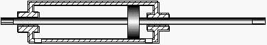
The ISO schematic symbol of this cylinder is as follows:
![]()
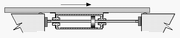
In the following figure, we see a configuration of the double rod cylinder used to drive a tray in a to-and-fro reciprocating motion:
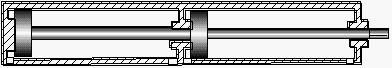
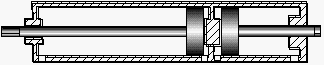
b. Tandem Cylinder
A tandem cylinder is similar to normal single rod cylinders, but has two or more chambers inside it. The figure below shows a simple two-chamber tandem cylinder. The advantage of such a cylinder is that it can provide almost twice the force as a single cylinder with the same diameter. Of course, it can move only about half the maximum motion of a same length simple cylinder system (why) ? It is used when there is a space restriction making it difficult to locate large diameter cylinders.
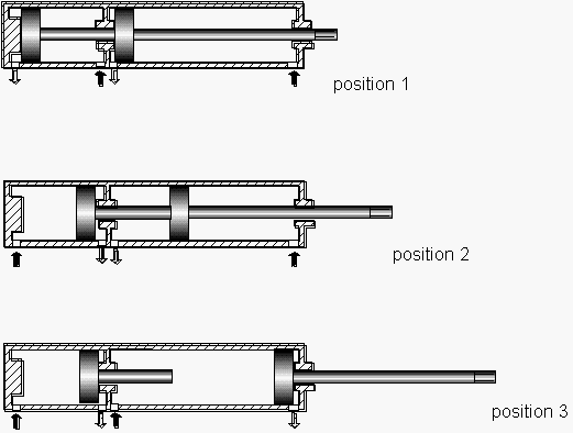
c. Multiple Position Cylinders:
Up till now, all cylinders we have studied can only stabilise in one of two positions: ON and OFF (or ‘+’ and ‘-’). There are configurations by which the same cylinder can in fact move through more than two steady state positions. Two different designs of such cylinders are shown below. These cylinders can be used in multi stage setups. For example, in automatic testing of electronic boards, where two/three different testing heads can be used, one after the other, after fixing a electronic board on a single fixture, and moving the fixture using a multi-stage cylinder. Another example is multi-stage assembly heads for more than one insertion operation using the same fixture.
i. Type I
The filled arrows show the supply of pressurised air into the cylinder ports. The cylinder shown can move the piston through three stages:
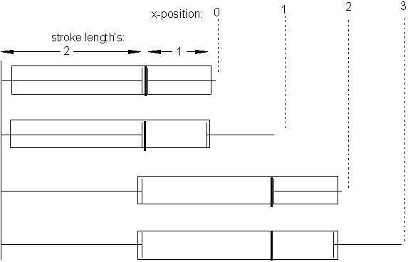
ii. Type II
The other alternative is achieved by mounting two single-rod cylinders together, back to back. In this configuration, the cylinders cannot be fixed, but by fixing the extreme piston rod, four positions can be achieved. In fact, by using multiple cylinders attached in this way, you can get 2n positions, for n-cylinders (how ?) !
3. More types of Valves
a. Shuttle valve
Very often, to make a pneumatic circuit work, we need a valve that either one of two supply lines to provide compressed air to a device. This has some nice applications in generating logical connections (especially OR relations) using purely pneumatic systems. The shuttle valve is shown schematically below; later, we will show an application of this type of valve.
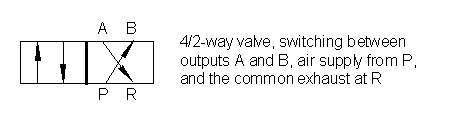
b. 4/2 way valve
In controlling double-acting cylinders, one may use either a 5/2-way valve (as used by the cascade logic), or get a 4/2-way valve, which has a common exhaust port. The schematic is shown below:
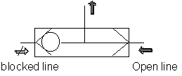
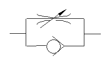
c. Flow restriction valve
Sometimes, we need a small delay between one event (such as extension/retraction of a cylinder) and another. To obtain such a delay, a special valve called a flow restriction valve is used. The physical principle of such a valve is simple: it merely makes a constriction in the path of air flow, to allow only a small opening. Thus the air flow is restricted, causing expansion of air and a (temporary) reduction in pressure across the valve. After a while, the volume of air across the valve builds up, thereby restoring normal line pressure. The constriction of such a valve is usually adjustable, and therefore different time delays can be achieved (to fine tune the valve until the pneumatic circuit works as required). The ISO symbol for flow restriction valves is shown below:
Other valve classifications:
Apart from the different valve functions, they are also sometimes classified by how they are activated. You have already seen many different ways of activating valves (example: using pressurised air, solenoid, manual levers, spring etc). Here are some more terms related to valve activation.
a. Monostable/Bistable valves
Monostable valves have one side activated by a spring, and the other by any other means (example: solenoid). Therefore, when the solenoid is OFF, the valve will return to the spring-side position by itself. Such valves have only one stable positin when they are inactive, and are therefore called monostable.
On the other hand, valves with both ends activated by means other than springs (that is, no spring used on either end), can stay in either end when the valve in inactive. These are called bi-stable valves. In such valves, it is necessary that at any time during operation, one, and only one end must stay activated ! (Recall how this is achieved by the manifold connections in the Cascade logic).
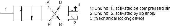
b. Fixed Position Bistable (non-floating) valves
Among bi-stable valves, a small mechanical lock is sometimes added to ensure that the valve will stay in the end which was activated last. The activation of any end is strong enough to dis-engage the lock, and move the valve to the required position, where it again locks. The following figure shows the schematic of such a valve.
4. Other useful pneumatic functions
a. Executing the OR logic using pneumatics
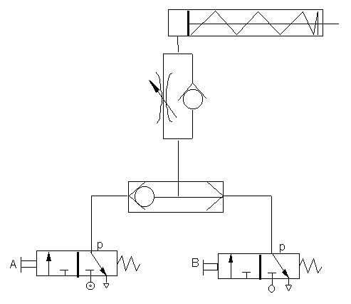
The above example shows two different (and common) functions. The shuttle valve ensures proper logic for switching ON the cylinder. The logic is: A OR B. Thus, either operating the left side 3/2-way valve through pedal A, or the right side 3/2-way valve using pedal B, the pressurized air will reach the cylinder. Not that if we did not use the shuttle valve, and instead, directly connected the ‘p’ port of both valves through a T-joint air pipe, then the pressurized air from either valve would escape from the exit port of the other valve.
Secondly, the flow restriction valve allows us to introduce a small time delay between the time either valve is activated, and the cylinder is extended.