Manufacturing Systems and Mass Customization
In the final lecture of this series, we shall briefly introduce one future trend on modern manufacturing: Mass Customization. The practice of mass customization has occurred in industry for a decade or more already, but the widespread use has only become popular due to a couple of new trends: (1) the importance of the customer demands and taste, and (2) the ability to get individual customer demands to the production line, and manufacture based on this information.
The prominent use of this is in computer industry, and automobile industry. (There are other industries, such as airline manufacturers, who customize each product, but they are not necessarily mass producers).
Let's look first at the definition of the terms mass customization:
"Mass Customization is a new way of viewing business competition, one that makes the identification and fulfillment of the wants and needs of individual customers paramount without sacrificing efficiency, effectiveness and low costs" [Pine 93]
As you can see, the definition is as recent as the systematic study of this trend. From a production point of view, the study of MC is even more recent; the definition:
"Mass Customization is interpreted as the process of reflecting very specific and varied customer requirements within a high volume production process without affecting lead time, cost or quality" [Beaty 96]
In order to achieve MC, the new product realization process must consider two aspects: how to design products that are offered to the customers, as well as how to design manufacturing facilities and equipment so as to achieve low cost flexibility. In this lecture, I shall introduce the material related to each of these topics. Since our own department has been active in this research, the work presented is a summary of research done at HKUST.
Product Design for Mass Customization
The issues here are the following:
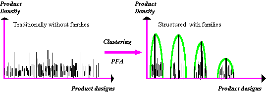
Each customer has individual tastes and preferences. Therefore, there should be many design choices that must be available to the customers. From a production and logistical point of view, however, we would like to restrict the design choices to as few as possible, to achieve cost efficiencies. Therefore, the problem of Design for MC translates into the development of product variants that can be efficiently manufactured. Tseng's group proposes application of Suh's axiomatic design theory to develop the concept of Product Family Architectures (PFA) for this. The approach is broadly based on the optimization of the two conflicting objectives: product variations and manufacturing economy. Group Technology was used by them to generate clusters of designs (product families), and then further sub-division of the designs, to create a PFA.

Figure 1. Forming PFA's
How does Suh's theory apply to formation of PFA's ?
Here is a simple comparison:
Traditional Design Methods:
1. Form FR'
2. Suggest DP's,
3. Follow Suh's Zig-Zag process to get a Decoupled design
Mass Customization:
1. Study product family and variations;
2. Form FR clusters (ranges, or step-sizes)
3. Design modular DP's for each range of each FR.
4. Define product family architecture constraints.
Let's look at some of the important steps in the formation of PFA's (more details are given in the following paper: Tseng, M. M., Jiao, R. J., "Design for Mass Customization," Annals of the CIRP, vol. 45, no. 1, 1996)
Study product family and variations:
In this step, the entire range of products of a company is studied, and potentially clustered into product families. Concepts of similarity, and Group Technology are useful in this step. Further, at this stage, QFD type of principles may be used to get an assessment of ranges of products or product functional requirements. QFD can also give some sense of the combinations of different FR's that are considered important from the customers' standpoint. Often, the first step may lead to maximal ranges of values of some FR's. If one knows the range of values, it may be useful to be able to divide this range into several steps. The idea here is to generate several discrete design options, rather than giving the customer a continuous range from which to choose. Pahl andBeitz developed an excellent and comprehensive set of guidelines to generate such step sizes. The basic approach is to provide product ranges in step sizes of a range, such that each subsequent item of the range is a constant factor times the previous in value. Example, motors which have power ratings of 1 HP, 2 HP, 4 HP, 8 HP etc. Some amount of care must be taken in generating such a range using the geometric series method: some properties of materials do not scale up and down by the same factors (e.g. if a disk size is doubled by doubling its radius, then its weight will become 4 times of the original!)> Further, some components of each design are standard parts, for which it is better to use the closest standard size, rather than the exact scaled value.
The next step follows Suh's practice: design a DP for each FR in each range of sizes, using the standard zig-zag method. Each DP must be modular, and the overall product design must be such as to allow several alternative DP's to plug in to provide the functionality.
The final step involves generation of the product family generation constraints: an actual product design can be generated by selecting from one of many DP's that will provide a given FR specification. Such constraints define which DP's can or cannot be assembled to function together with other DP's (satisfying different FR's). Therefore, once the actual FR specs of a customer are known, alternative combinations of DP's that will closest match his needs can be generated and their respective costs presented to the customer.
Manufacturing Issues in Mass customization
The design of manufacturing systems equipped for mass customization must consider two aspects:
1. The tooling at each assembly workcenter can be redesigned to offer rapid turnaround and high efficiency; and
2. Assembly lines can be redesigned and made flexible to allow quick turnaround and high throughput rates.
The first issue looks at the re-design of manufacturing/assembly equipment at the workcenter level. Individual machines and mechanisms are re-designed to enhance their flexibility. The second issue is concerned with global optimization and planning of assembly/production lines. Here, we may consider what tooling to equip the workcenter with, in order to achieve faster turnaround, without having to spend undue waiting time (or fabrication lead time) for new equipment. In the worst case each workcenter could be equipped with one of each kind of tools -- this can increase the flexibility, but at a tremendous cost (and space).
We shall focus on assembly systems. typical assembly equipment may be classified into one of the following five categories:
Further, we shall only address the problem at the equipment level in this lecture. In other words, our objective is:
To develop a systematic procedure toredesign the existing tooling in the assembly work cell into a new class of Modular, Parametric Assembly Tool Set (MPATS) that can offer quick turnaround during product switching and also can operate at the same throughput levels as hard automation
Notice that we have proposed two different techniques to achieve flexibility; we further elaborate on these:
Modular design strategy: Redesigns the existing tooling into a set of independent 'plug-and-play' modules
Parametric design strategy: Redesigns each module with adjustment capability for different sizes of the part family
In order to illustrate the MPATS technique, we shall pick examples of hard tooling used commonly in mass production, and convert them into MPATS designs. Several such devices have been developed in our labs, and we shall show some figures demonstrating them.
The three examples chosen belong to three different categories of assembly automation devices: (a) vibratory bowl feeders, (b) non-vibratory feeders, and (c) robot gripper systems.
Vibratory feeders:
Much research was done in the previous decade on vibratory feeders by Geoffery Boothroyd and his group; this has been reported in their excellent text [see reference below]. We begin by introducing their bowl feeder, and two examples of hard tooling used to orient and feed parts using bowl feeders.
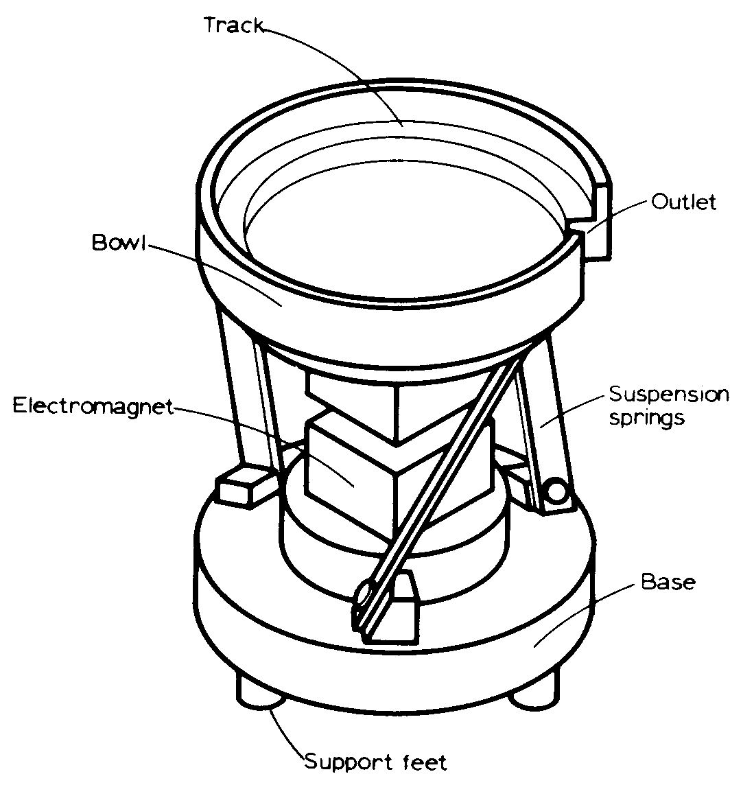
Figure 2. A vibratory bowl feeder [source: Boothroyd 92]
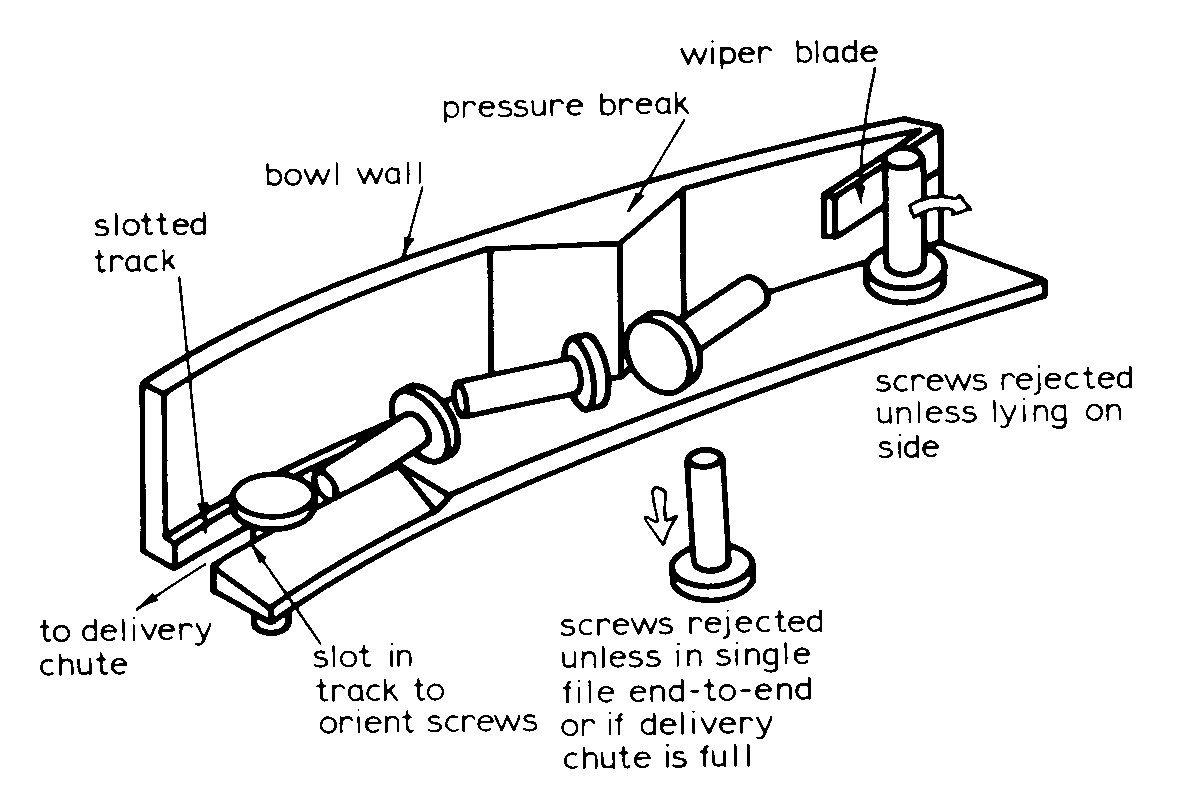
Figure 3. Hard automation: devices on bowl to orient and feed screws [Boothroyd 92]
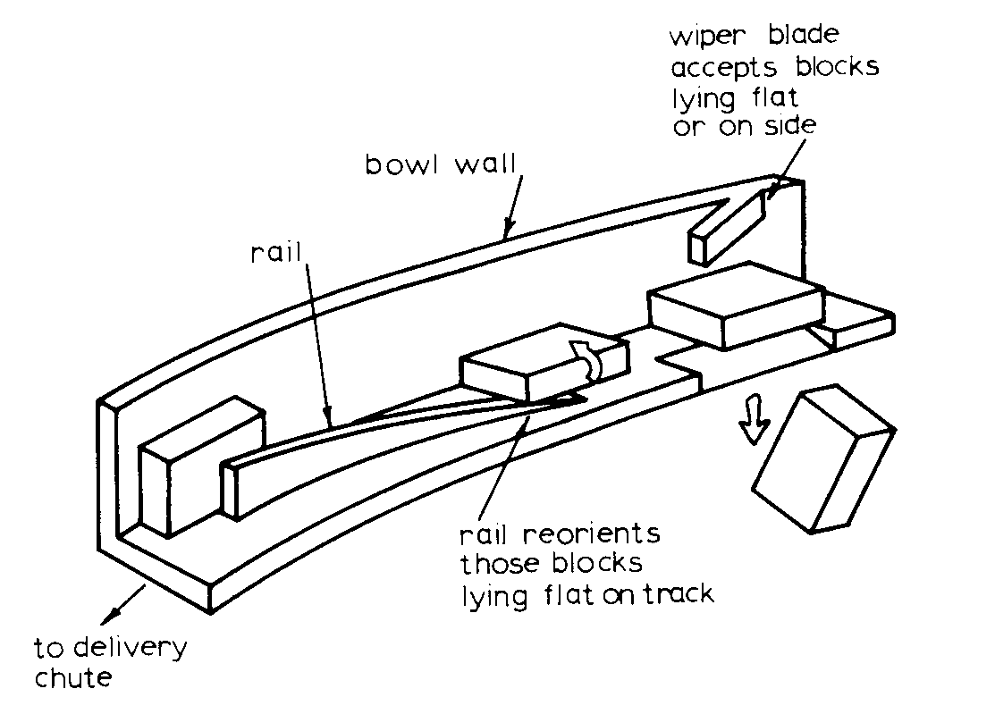
Figure 4. Hard automation: devices on bowl to orient and feed blocks [Boothroyd 92]
The standard usage of bowl feeders in hard automation has been characterized by "one-bowl, one-part". If a different part needs to be oriented and fed using a bowl feeder, a new bowl needs to be equipped for this task. The MPATS strategy suggested the re-design of the bowl, including a fitted standard sized base plate, with bevel-slots to accept different orienting modules. Each orienting device, e.g. the wiper blade, slotted track etc, is re-designed as a parametric module. By changing the module type and sequence in the modular base, we can use the same bowl to feed/orient different part types. Further, different sizes of the same part type (e.g. screws) can be oriented by merely changing the parameter values of the individual modules). The design below shows the MPATS bowl, the modular base, and the devices used for orienting screws. The typical time required for changing a module in the system is less than one minute.
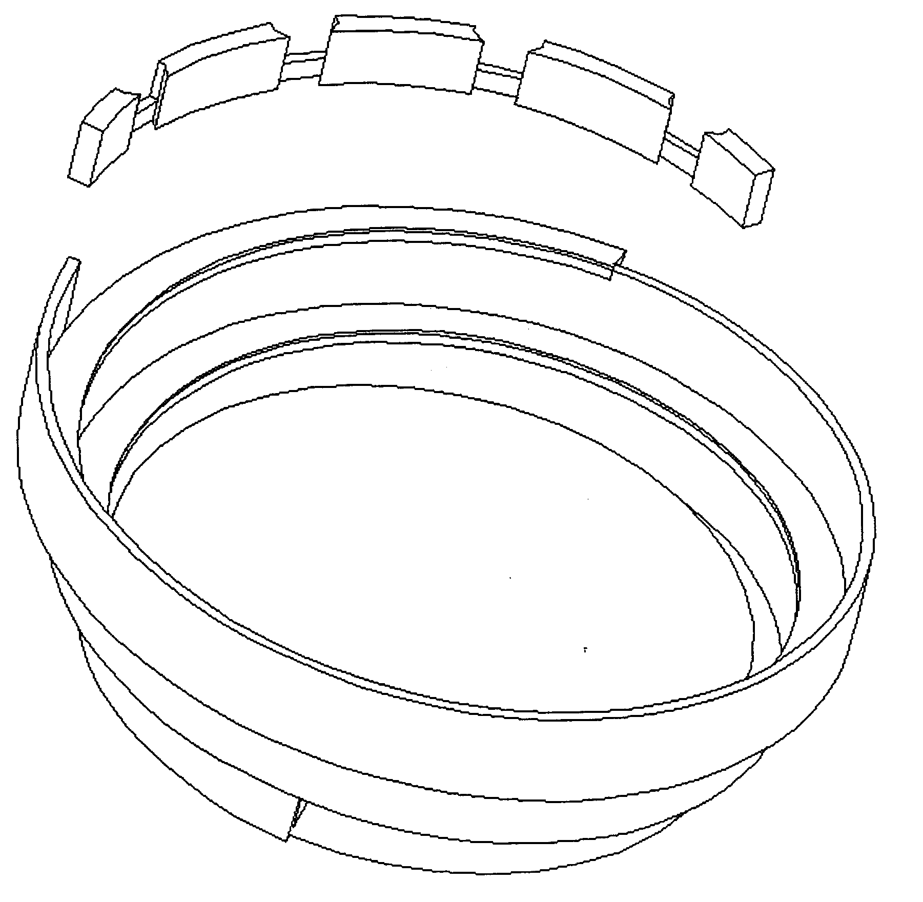
Figure 5. MPATS vibratory bowl, with modular base (exploded view).
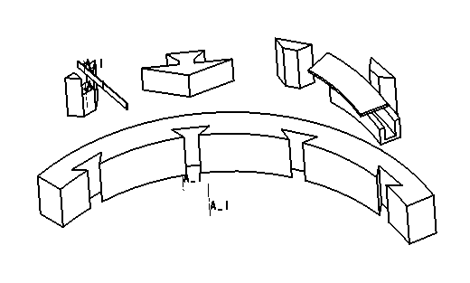
Figure 6. Modular, Parametric devices and the Modular base
The figure above shows the MPATS devices in an exploded view. These devices are, in sequence, an MPATS wiper blade, a modular pressure break, a spacer, and an MPATS slotted track (from left to right). A typical shop would have several more such devices, which could be randomly placed and adjusted along the base, to orient and feed different shapes and sizes of parts.
The MPATS methodology
Before embarking upon the details of the other classes of devices, we digress shortly, to look at the broad methodology that we derive from our experiences in developing the vibratory feeder. The methodology turns out to be quite general, and will be used in the development of the other devices. The next figure shows a flow chart of the main steps.
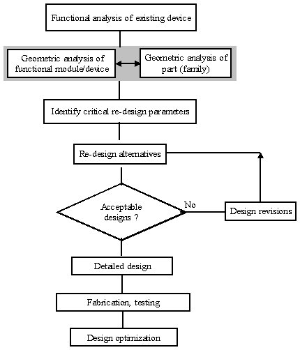
Figure 7. The MPATS design methodology
Non-Vibratory feeders
The above MPATS strategy is quite broad in application: we now demonstrate its application to a different type of feeder -- a rotary feeder that is used for cylindrical parts. The base design is once again borrowed from one of Boothroyd's text:
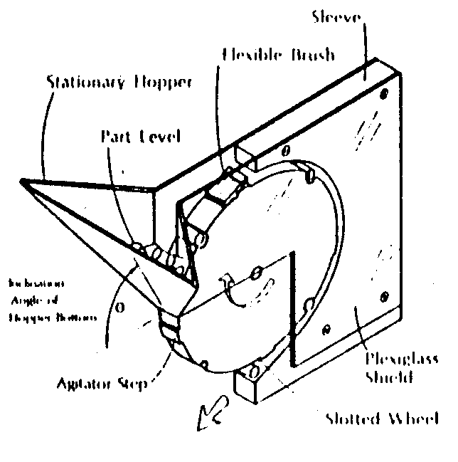
Figure 8. A Rotary Hopper feeder
The design works as follows: cylindrical parts are dumped into the hopper, and the slotted wheel set into rotation. The agitator step stirs up the parts in the hopper, and some parts that are properly aligned to the slots in the wheel settle into one of the slots. Parts that are not properly lodged are brushed back into the hopper. the oriented parts are dropped off into the chute at the bottom side of the feeder.
The basic strategy towards making this design modular and parametric involved getting the functional features, the slots of the wheel, to be modular and parametric.
We achieved this by two tricks: the wheel was equipped by a series of different sized slots; a sleeve was designed around the slotted wheel such that in any position of the sleeve, it would expose only those of the slots on the wheel that were of the same size. By adjusting the sleeve, one can easily set the feeder to handle parts of different radii. Further, the sleeve could be fixed along different axial locations, allowing the ability to parametrically handle parts of different heights. These basic ideas are captured in the two figures below. The wheel shown in the figure has slots of two different sizes.
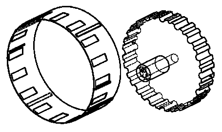
Figure 9. The slotted sleeve and the Modular slotted wheel
MPATS Robot Gripper
The final example of the MPATS group of tools is a flexible robot gripper system. Typically, robot grippers are either very simple, non-flexible, single degree of freedom, pick and place type of devices. Alternatively, they are extremely sophisticated, multi-articulated fingers with sensory feedback, capable of handling a variety of very complex tasks. The MPATS gripper system was designed for flexible assembly operations. The gripper system therefore needs to handle a variety of parts, but the task it is expected to do is typically a simple one. Based on these specification, the MPATS gripper system was designed with a two layer automatic change system: the gripper first can select from a set of different actuator types (rotary or linear actuators, powered either by electricity or by pneumatics). After having selected the actuator, the system than selects the proper tool (end effector) and automatically fits itself with the selected tools. It then goes about performing the operation required.
The system is pictured in the following figures, which show the different connectors that make up the hardware. The system has currently two actuators: a linear pneumatic actuator, and an electric screwdriver. The pneumatic gripper can use one of three pairs of fingers, to pick cylindrical, rectangular, or odd shaped parts. The screwdriver can use one of four different types of screwdriver bits (including Philips, Hex-head, Flat). An integrated force sensor is used to control the z-direction motion coordination during screwing/unscrewing operations.
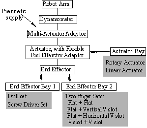
Figure 10. Schematic diagram of the MPATS gripper system
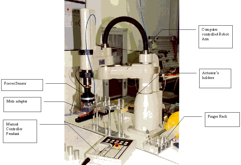
Figure 11. The MPATS Gripper System used by an ADEPT Scara Robot
The material for this lecture reports some of the work done in the Mfg Sys Lab, Dept of IEEM, HKUST over the past few years, by Dr. Joneja in association with Dr. Neville Lee and several students including James Leung, Thomas Wu, B. Rao, Eric Chan and K. K. Yan.
References:
Assembly automation and Product Design, Boothroyd, G., Marcel Dekker, 1992
Beaty, R.T., 1996, "Mass Customization" Manufacturing Engineer, pp. 217- 220
Pine II, B. J., 1993, "Mass Customization: the New Frontier in Business Competition", Harvard Business School Press, Boston