An Introduction to Rapid Prototyping
Building a prototype of the designed product is an important step in the product realization cycle. The goal of any firm is to reduce the time/costs associated with this process. The reasons are many:
Problem:
How do we reduce the product realization time ?
These notes present an important new technology which can help in the first of these approaches:
Rapid Prototyping -- as an approach to reduce product realization time.
We have seen that a significant amount of effort and time is used in the development of the mock-up models, and the prototypes of the new design. Many of the parts made during this process need not undergo the testing conditions that the final product must.
In other words, many of the components of the prototype need not adhere to the final product specifications.
If it is possible to manufacture these components, geometrically (if not structurally -- that is, in terms of strength, finish etc.) very quickly, then significant time savings may be made.
Typically, fast prototypes can potentially be used for the following:
To see what the object looks like, especially a consumer item that must look appealing when painted and packaged.
To make sure that the part fits to, and works with other parts to which it will be assembled.
To make a casting mold which can then be used for full scale production.
The advance of CAD/CAM integration was the first step towards rapid part manufacturing.
However, a completely new technology, now called Rapid Prototyping, has been very successful in making quick models of even very complex geometric shapes in extremely short times.
This technology has many different manufacturing processes. The main ones of these are:
We shall study each of these in short detail, and also see how each of these is integrally connected to CAD systems. This last fact shows again the importance of solid modeling to the product realization process.
1. Stereolithography
Stereolithography is used to make models (prototypes) out of special materials called photo-reactive resins. The resins are synthetically manufactured, and are normally available in liquid form. However, when exposed to over a certain intensity of particular radiation (usually Ultra-violet light), they solidify.
The method works in a simple fashion:
1. The solid is constructed by first breaking its geometry into a series of very thin layers.
2. The manufacturing process will build the solid by building each subsequent layer, from bottom to top, such that the neighboring layers are fused together.
The process is as follows:
There are two different methods used to exposed the selected area of the resin surface to UV light.
3D SystemsTM Inc. use a UV Laser to 'scan' the area, similar to raster techniques used in television sets.
Specs of their best machine, the SLA-7000TM
Laser: Argon ion
Model Size: 20x20x24 inches
Resolution: ±0.001"
Price: US$ 300,000-$400,000
Another manufacturer is Aaroflex Inc , whose machines have similar specs; the claimed resolution is 3000 DPI, which is approximately 0.003".
Method:
The laser scans the layer at those areas where the layer is solid.
The solidification of the polymer is in two steps: the laser is intense enough to polymerize the resin -- which becomes solid.
Once all solid layers are built, the part is put in an oven, and heated for a longer duration to cure the polymer to its final hardness.
The figure below shows example parts generated directly using the 3Dsys SLA machine (source: 3D Sys home page:)
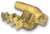
Figure 2. Automobile Manfacuturing (Manifold prototype, Rover Group, England)
[source: www.3dsystems.com]
2. Solid Ground Curing
CubitalTM Inc. uses an optical mask (similar to electronics manufacturing) to expose the entire area on the surface at the same time. (Implication: faster).
Specs of their best machine, SGC 5600TM:
Model size: 20x14x20 inches
Accuracy: 0.1% of model size, up to 0.0033"
Layer thickness: 0.004 to 0.006"
Resolution: 0.004"
Price: US$ 470,000
The methodology is as follows:
1. A resin applicator covers the work area with a film of photoreactive liquid polymer resin
2. A negative image of the slice is printed on a flat glass plate (just as a laser printer prints an image on a paper). The image on the glass forms an "optical mask"
3. The optical mask is placed above the work area under a high-power UV lamp
4. A shutter opens for a few moments. The exposed resin is flooded with UV light -- which can polymerize AND cure the resin.
5. The optical mask is wiped clean
6. Unused (liquid) resin is vacuumed out of the work area
7. A film of melted wax is spread over the work, replacing the liquid resin, to fill any cavities.
8. A chilled plate is pressed down to solidify the wax
9. A milling disk flattens the layer and trims it down to required thickness
10. The model is lowered one layer thickness, and the process repeated.
The following figure shows examples of Cubital capabilities.
[Source: Cubital Inc.]
Another company using a similar idea, but different technique is Sanders Inc. They use a variation of the ink-jet printers to deposit thermoplastics or wax, layer by layer, to create the solid. The schematic [source: www.sanders-prototype.com]
Their machine, MODELMAKER II, has the following specs:
Model size: 12x6x9 inches
Accuracy: 0.0005" (very good !)
Surface finish: 32-63 micro-inches (very good !)
An example part, also from their web site, is shown below.
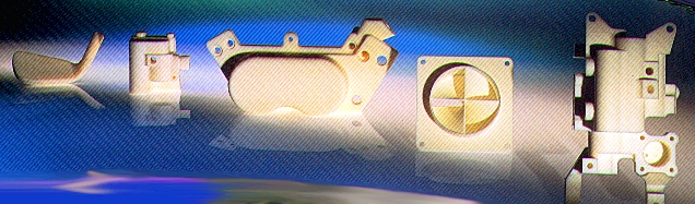
Selective Laser Sintering
These systems try to extend the well known methods of metal sintering. Sintering uses a metal powder, which is compacted into the required shape via a mold, and then heated in an oven to just below the melting point of the metal, whence the powder particles unite by a process of diffusion. In this case, the sintering powder is specially coated with a very thin layer of thermo-plastic (melts at higher temperatures) resin. When the laser beam heats the powder, the resin melts, causing the powder to glue together. The areas where the laser does not pass remain powdery.
The technology is marketed by DTM Corp., whose best machine is:
Sinterstation 2500TM
Laser: 50 watt, CO2
Spot size: 0.015"
Tolerance: ± 0.01"
Model size: cylinder, 12" dia, 15" high.
Speed: 0.5" to 1" per hour
Price: ~ US$ 400,000, plus yearly maintenance: US$ 90,000.
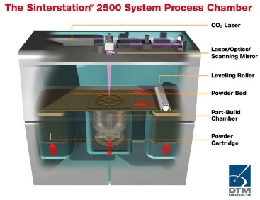
[source: DTM Corp.]
Method:
1. A layer of powder is deposited on the platform.
2. The CO2 laser passes over the areas of the layer to be solidified.
3. The platform is lowered, and a new layer of powder is spread on top of the old layer.
4. The process is repeated.
5. At the end, we have a solidified model, and the remaining powder can be shaken off and re-used.
6. The model is heated in an oven to a temperature just below the melting point of the metal powder. At this temperature, the resin burns away, and the metal powder gets united due to diffusion, into a solid form.
7. Since the sintered model has low density, often some lower melting metal, such as bronze, can be diffused into the pores to make it heavier/stronger.
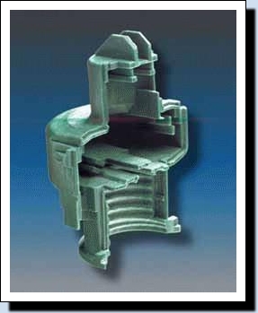
Examples of the DTM's parts can be seen in the figures below. [source: www.dtm-corp.com]
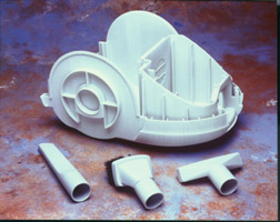
Material: plastic; [source: dtm-corp.com]

Metal Injection mold [source: dtm-corp.com]
Fused Deposition Modeling
FDMTM is a patented technology of StratasysTM Inc. This technology works as if writing a 3D part through a pen, layer by layer (hence the name, fused deposition).
Machine specs of the FDM-8000TM:
Model size: 18x18x24 inch
Resolution: ±0.005 inch
Wall thickness: 0.009" to 0.25"
Repeatability: ±0.001"
Price: US$ 180,000
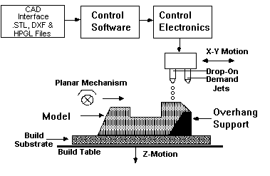
The machine looks like a box with an enclosed pen plotter. The pen of the plotter lays down heated plastic or wax (instead of ink), building the model up in successive layers.
A 0.05" filament of thermoplastic material is pulled from a spool into the pen, where it is heated to 1şF above melting point, and extruded through the pen nozzle. It solidifies soon after getting extruded, and stick to the layer on top of which it is deposited.
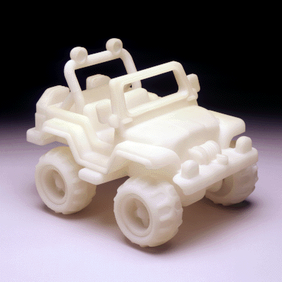
The figure below shows the process capabilities of real working prototype room humidifier built and tested using the Stratasys machine. [Source: www.stratasys.com]
Lamination Methods
Helisys Inc. used a method of gluing together sheets of paper and foil, cut in the shape of subsequent layers to produce the part. The cutting of each layer is done by a laser.
Helisys is now shut down, but they operate under a new company called Cubic Technologies.
The specifications of their best machine, LOM-2030H:
Model size: 32x22x20 inches
Resolution: ±0.01 " overall
Laser: 25 watt, CO2
The figure below shows a Helisys LOM model and its use in a plaster casting process. [Source: THe helisys web page, now defunct]
MIT: 3D printing
In this method each layer begins with a thin distribution of powder spread over the surface of a powder bed. Using a technology similar to ink-jet printing, a binder material selectively joins particles where the object is to be formed. A piston that supports the powder bed and the part-in-progress lowers so that the next powder layer can be spread and selectively joined. This layer-by-layer process repeats until the part is completed. Following a heat treatment, unbound powder is removed, leaving the fabricated part.
The technology is licensed to several companies, including Soligen, Inc. This company uses a process called Direct Shell Production Casting (DSPC) to create ceramic shells corresponding to the casting mold for the part. The mold model is enhanced by addition of gating and runners, and then built using the 3D printing process and a ceramic powder. The resulting part can be used to pour molten metal to directly create the part.
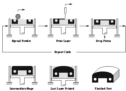
The 3D printing process [source: MIT 3D printing lab]
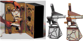
The following is an example part manufactured for General Motors by Soligen's DSPC technology [source: www.soligen.com]

Engine manifold for racing car
Software support for Rapid Prototyping systems
Almost every modern solid modeler supports rapid prototyping systems. The most common method of storing solid models for RP systems is in a format called STL.
The STL file is created by a method called triangulation. In this, the entire surface of any solid model is approximated by a series of triangles. The method to do this is well known in computational geometry, and the algorithms are very efficient.
The reason for triangulating the solid in this fashion is mainly the efficiency of computations for layering operations. To create hundreds, or even thousands of layers of a solid, one must repeatedly intersect the solid with a plane -- each such intersection operation can be very time consuming if the solid is made up of complex geometric shapes. However, with triangulated surfaces, this computation is fast, and therefore the RP system can generate all layered information of parts with as many as 1 million triangular faces within a few hours!
For those interested in this technology, a good place to start is by browsing through the various links in the following site maintained by Professor Jan Bohn of Virginia Polytechnic University.