Introduction to CAD: part I
A sculptor can convert a mental image into a sculpture of an object. Most
machinists, however, are not sculptors. Any design that exists in the mind
of a designer must be clearly specified to the machinist in order to create
the part.
What information is required to make a part, and why? How can we store this
information in a computer? These issues are covered in this lecture.
What information is needed?
We shall be concerned mainly with models of object. X models an object A
if X can be used to answer some questions about A. Therefore, to know what
information is needed, we need to know what kind of questions we need to
ask about our object. In most cases, we are satisfied with information about:
2-D drafting
To specify the geometry of the part, we need to define the shape
and the size.
2-Dimensional object:
Model: draw the outline on a piece of paper.
Problem: What if the object is very large?
Model: drawing to scale
So the first important concept we notice is that of scaled drawings.
3-Dimensional object:
Model: 3D replica.
Problems: how do we manufacture the replica? Will it cost too much to make
replica? Will it require too much time ? How do we scale back from replica
to full size?
Model: make a drawing on paper.
Problem: How do we represent a 3-Dimensional object in 2-Dimensions?
Model: a sketch.
Problems: What if the designer is not a good artist? Sketches become dirty
and unreadable for complicated objects. Ambiguous for complex shapes.
Model: an engineering drawing.
A drawing that is (a) made to scale (b) using instruments (ruler, compass
etc), (c) following a fixed set of rules to represent the various
geometric properties of the object(s) drawn.
Most engineering drawings are geometric projections. The most popular
method (set of rules) to draw engineering drawings is orthographic
views.
Orthographic views
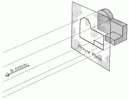
Orhtogonal projection (note the Picture Plane) [source: FV 133]
Othogonal views [source: CAM 18]
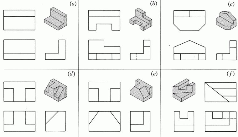
Several examples of orthogonal views [source: FV 145]
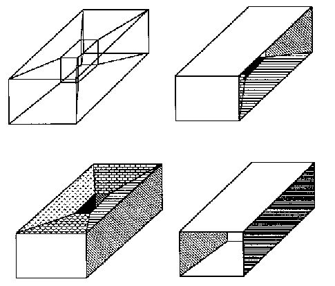
Sections:
An important and common method to show more details of a drawing (and to
make it easier to understand) is sectioning. A sectioned view is basically
used as an additional view of an object, showing how it would look if a knife
was used to slice it along the sectioning plane.
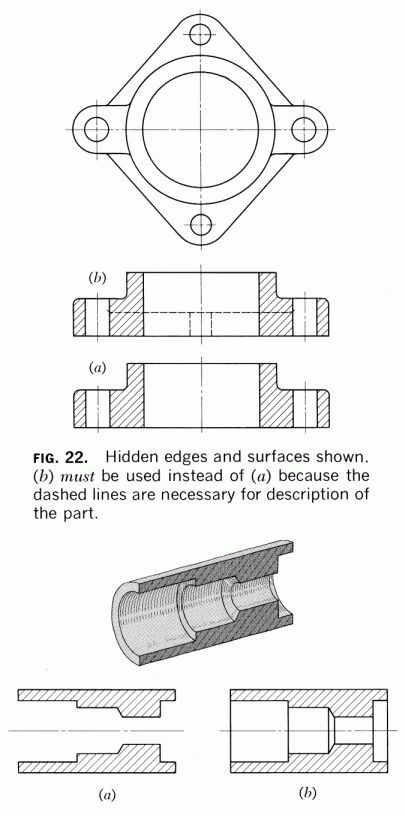
Section views [source: FV 243]
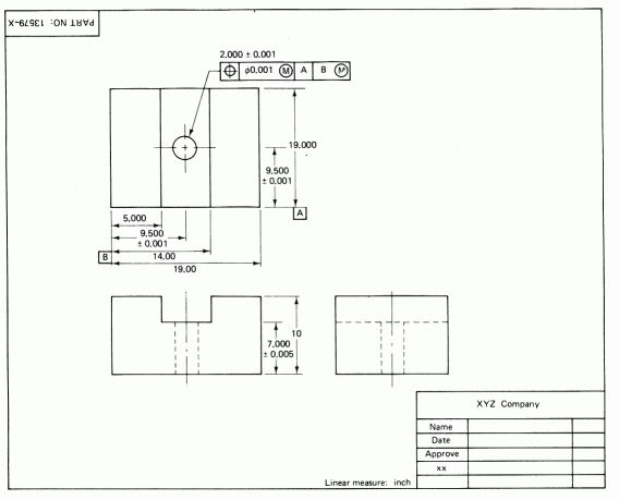
Dimensioning
A machinist can take an engineering drawing, and machine it. Since it is
made to scale, he may have no difficulty in measuring the length of each
line, and multiplying it with the scale factor to get the exact length.
Problems: Measuring each length during machining can be tedious; despite
all the care taken in drawing, there will be errors if such a process is
used (drawing errors, measurement errors). Therefore, each engineering drawing
is dimensioned, that is, all the necessary lengths of the various geometric
entities are written on it.
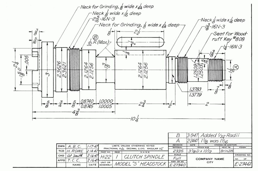
A Dimensioned Drawing [source: FV 370]
Dimensioning Guidelines:
- Show enough dimensions so that intended sizes can be determined without
calculations or assumptions
- State each dimension clearly so it can be interpreted in only one way
- Show the dimensions between points, lines, or surfaces that have a
necessary and specific relation to each other
- Show each dimension only once
- Dimension each feature in the view where it appears in profile, and
in its true shape
- Use standard sizes and tolerance values where possible
Problem: Can we really manufacture parts to the exact dimension that is specified?
No. Therefore, we need to specify tolerances.
Tolerance types and specification
Why do we need tolerance specification ?
- No manufacturing process is perfect.
- Functional Requirements (designed tolerances)
Examples: Bearings; Press Fit Components; Assembly ease (loose/running fits);
Nominal Size: the size of the designed feature as shown on the drawing.
Basic size: == nominal size, except that nominal size is shown in
decimal notation to third decimal point or beyond.
A typical tolerance on a dimension is shown by the limits on the size:
10.000 ± 0.003
The representation can be Unilateral, or Bilateral.
Unilateral dimensions have both of the tolerance values ≥ 0.000
(or ≤ 0.000).
Bilateral dimensions => both tolerance values are non-zero, and
of opposite sign.
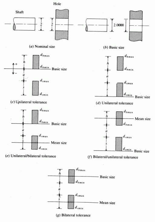
Tolerance specifications [source: Z 760]
Limits and Fits
Three types of fits are commonly used in assembled parts: Loose (or running)
fit, Transition fit, and Interference (or force) fit.
Examples of Use:
Loose fit: Shaft type bearings of large turbines;
Transition fits: Accurately assembled parts ( precision bearings);
Interference fit: Ball-bearing on shaft, pulley on shaft.
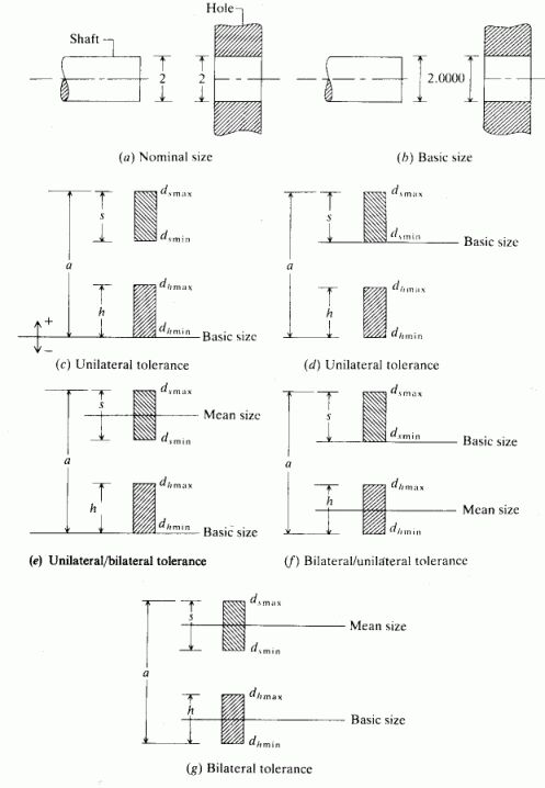
Specification of Limits [source: Z 762]
When the designer decides on the basic size, and the type of value. The allowance
is the difference between the maximum material conditions of the fitting
parts (e.g. the difference between the maximum allowed size of the shaft
and the minimum allowed size of the hole). The value of the allowance therefore
is an indication of the type of fit.
With this information, the dimensions can now be put on the drawing. There
are two conventions used in writing dimensions on a drawing: LMC (Least Material
Condition) and MMC (Maximum Material Condition). Depending on whether MMC
or LMC is used, the values of the limits are placed differently on the drawing.
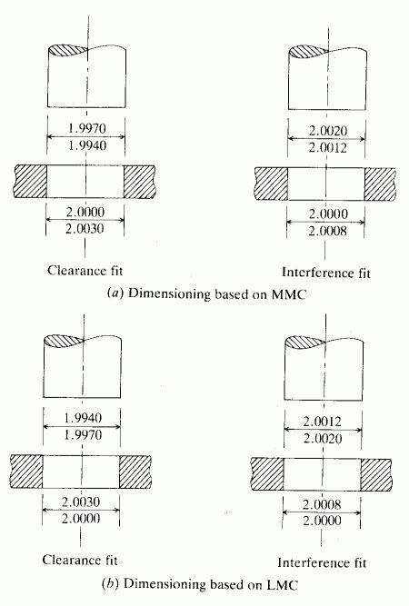
specification of limits under LMC and MMC [source: Z 765]
Surface Quality
Tolerance specifications are basically used to ensure some functional property
of the assembly, or of the assembly process. Once the tolerance is known,
the manufacturing process can be determined.
Another property that affects the quality and performance of any assembled
product is the surface quality. The surface quality therefore has to be specified
by the designer as well. Once again, the surface quality also determines
the manufacturing process that can be used to manufacture the designed part.
Surface roughness is defined in one of many ways: Maximum Roughness, RMS
roughness (root mean square), or Average roughness.
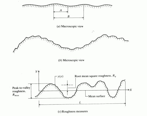
Surface Roughness [source: Z 773]
Average Roughness =
and
RMS Roughness =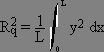
Geometric Tolerancing
Up till now, we have seen how to specify tolerances on linear dimensions.
However, geometric tolerancing covers the description of tolerances on other
geometric quantities such as variations on shape, which relate the tolerances
between lines (which were earlier dimensioned using conventional dimensioning).
Geometric tolerances are of three types: Size, Location, and Shape.
Size Tolerances:
Any feature with a shape dimension (such as a hole, slot etc) can be dimensioned
for size using conventional tolerancing.
Location Tolerances:
This type of tolerance is used to specify the location of some determining
point of any feature (such as center of a hole). The concept of True Position
is used here (as opposed to limits) to get appropriate shaped tolerance zone
(circular instead of rectangular).
Form Tolerances:
These are used to control all aspects of the form (shape) of the part.
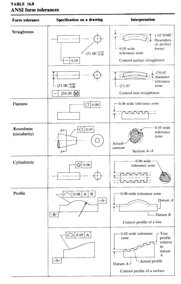
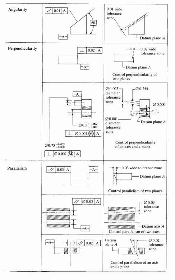
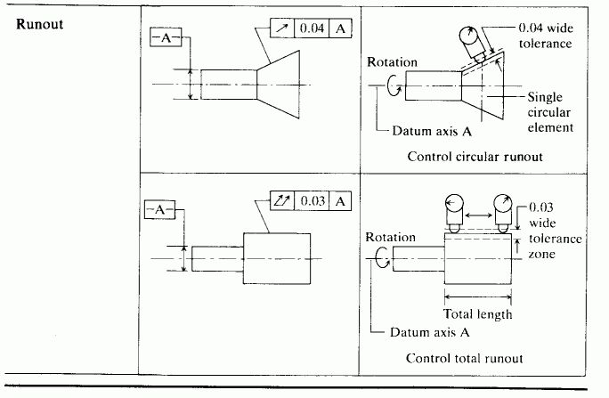
Form Tolerance Types [source Z 791, 792, 793]
Problems with Orthographic Views
(a) cannot reveal internal details of complex objects
(b) drawings sometimes difficult to read; difficult to imagine
shape of complex objects
(c) not a good format to display assemblies
Other types of engineering drawings: isometric views, perspectives, obliques…

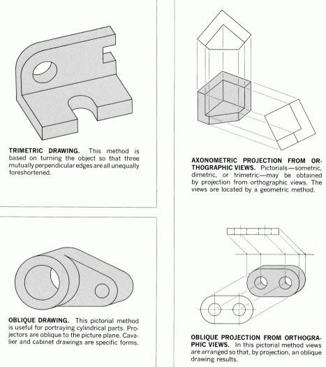
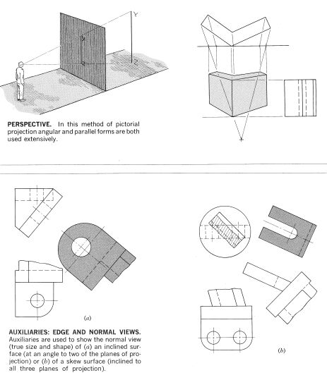
Other Common Drawing Types [source: FV 7, 8, 9]
Need for Solid Modeling:
Computerized Drafting (AutoCAD et al):
Saves on storage/retrieval;
Easy modification, update;
Problem: need to perform analysis (strength, shape, geometric, weight, center
of mass, center of inertia, etc.)
Solids Representation methods
Wireframe Models
problems: Ambiguity of representation.
Problems with wireframes [source: CAM 44]
Problem: how do we represent a solid using just a set of numbers (essentially,
within a computer, all we can store are numbers).
The two most popular methods of representation of objects for Computer Applications
are Constructive Solid Geometry (CSG) and Boundary Representation (BREP).
There are other methods, but we shall only concern ourselves with CSG and
BREP.
CSG
Concept: Most shapes can be generated using just a few basic (simple) shapes.
The selected set of basic shapes are called the set of primitives. More complex
shapes are generated by performing simple Boolean operations such as union,
difference and intersection. these operations are commonly known as Euler
Operators.
Some simple examples of CSG:
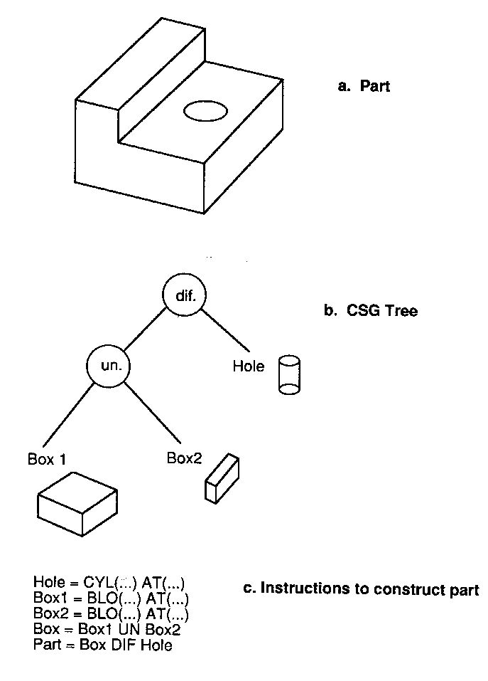
CSG representation for a simple part [source: CAM 49]
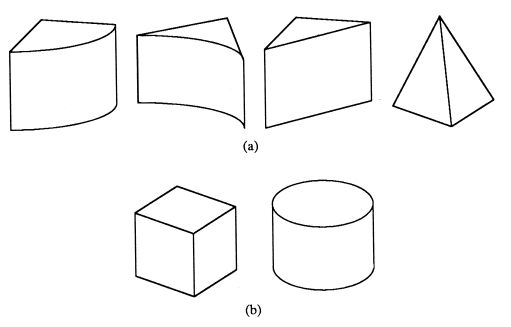
Alternative (equivalent) CSG primitives [source: M 83]
Problem: Is a system defined using a set of primitives and the (set theoretic)
Euler Operators closed?
The concept of regularized Boolean operations: why is closure over operations
important? To maintain uniformity of the data structures. (Why is that important
?)
The operators actually used in CSG modelers are known as Regularized Euler
Operators.
Problem with CSG:
- Non-Unique representation of same geometry;
- Difficulty of performing analysis for some tasks;
BREP
BREP, as the name suggests, is a boundary model. In effect, each entity is
defined by the elements that define its boundary -- till we reach an element
that has no boundary.
Since we're interested in representing solids, what entities define the boundary
of a solid?
What defines the boundary of surfaces?
What defines the boundary of curves (edges)?
What defines the boundary of points?
How is all this put together?
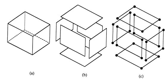
The boundary of a box
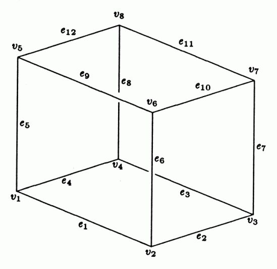
The geometric entities required for a solid model specification of a box
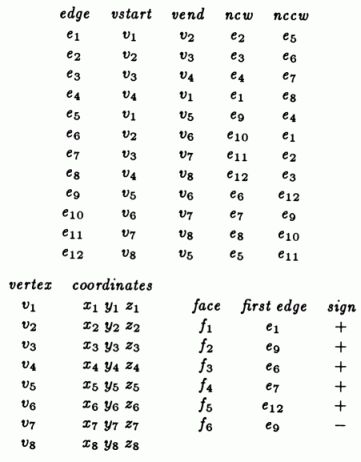
Double winged edge data structure for the box
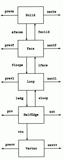
Pictorial view of the double winged edge data structure [source: M 103, 104, 107, 164]
Note: the figures in these notes have been copied from several sources. Each
of these books is an excellent source of information in their area -- so I encourage
you to buy them if you need to know more of these topics. The referneces are:
FV : Enginering Drawing and Graphic Technology, French and Vierck [now French, Vierck and Foster]
M : An Intorduction to Solid Modeling, Martti Mantyla
Z : CAD/CAM Theory and Practice, Ibrahim Zeid
CAM: Computer-Aided Manufacturing, Chang, Wang, and Wysk