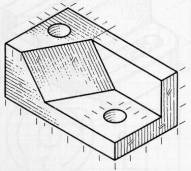
Q1 Draw orthogonal views for the object shown below; use these views to draw an auxiliary view that shows the oblique face in true size.
Q2 A unit cube is rotated and tilted and its orthogonal projection is drawn in full scale on the XZ plane. In the projection, the lengths of the three orthogonal edges are 0.8165, 0.8165 and 0.866, as shown in the figure (a) below. Find the direction cosines (see figure (b)) of each these three edges in the global coordinate frame.
Q3 The following figure shows the location and size tolerances on a hole in a part. To test if the part is acceptably manufactured, three cylindrical gauges will be used: The first two are the cylindrical 'go' and 'no-go' gauges to check if the hole size is larger than the lower limit, and smaller than the upper limit respectively. The third cylindrical gauge will be placed accurately on a positioning table, to test if the location of the hole center is within specified tolerance.
(a) What are the sizes of the 'go' and 'no-go' gauges ?
(b) Draw a figure to indicate the position and the size of the third gauge.
(c) Notice that the allowed position tolerance on the hole center
depends on the actual hole size in the manufactured part (because
of the MMC condition). Write the expression for the actual tolerance
on the hole position.
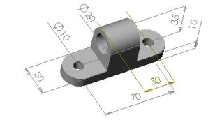
Q4 Using CSG primitives Block and Cylinder, show a CSG tree for the part below [note: all holes are concentric to the semi-circular ends].